True Position – Position Tolerance
GD&T Symbol: 
Definition:
True Position, or just Position as the ASME Y14.5 standard calls it, is defined as the total permissible variation that a feature can have from its “true” position. The “True Position” is the exact coordinate, or location defined by basic dimensions or other means that represents the nominal value. In other words, the Geometric Dimensioning and Tolerancing “Position” tolerance is how far your feature’s location can vary from its “True Position”.

Position is one of the most useful and most complex of all the symbols in GD&T. The two methods of using Position discussed on this page will be RFS or Regardless of Feature Size and under a material condition (Maximum Material Condition or Least Material Condition). However, since this is such a useful symbol, we will continue to add content and examples for other uses of this nifty little symbol in the coming months.
Application:
Although incorrect, we title this page and sometimes refer to the symbol as “True Position” since this is typically the term people are referencing when they are looking for the position tolerance. However, it is correctly termed in the ASME Y14.5 standard as simply “Position”. For clarity on these two terms check out our article and video here.

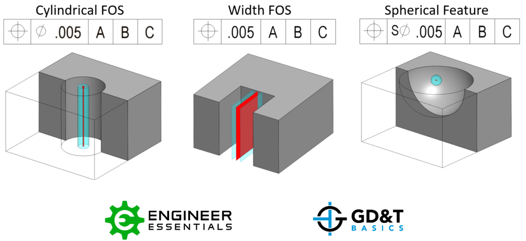
Position may be applied to any feature of size (Feature with physical dimensions like a hole, slot, boss, tab, or sphere) and control the central elements of these size features. See the above central elements of a hole, slot and sphere. Locating surfaces is to be controlled via Profile. Position can be used with Max Material Condition (MMC), Least Material Condition (LMC), projected tolerances, and tangent planes.
In the image below you can see how a hole is called out using the position tolerance symbol. However, this can also be applied to any feature of size in need of a location tolerance, such as a pin, a boss, or even a keyway. When you have a hole in a part such as a bolt pattern, true position is usually called out. It can be used almost anywhere to represent any feature of size.

Position in terms of the axis, point, or plane defines how much variation a feature can have from a specified exact true location. Again, True Position is the exact perfect location of the feature, located and oriented to the datum reference frame using Basic Dimensions.
Position Tolerance Zone
The tolerance is a 3-Dimensional tolerance zone that surrounds the true position. When specifying a position tolerance, datum features are referenced within the feature control frame. This means that you will have an exact point where the position should be with respect to a datum reference frame and your tolerance specifies how far from this you can be. The position is most often referenced with two or three datum features to exactly locate and orient the true position. If the feature of size is a cylindrical feature such as a hole in a part, the size value in the feature control frame is preceded by a diametric symbol to represent a circular or cylindrical tolerance zone.

The cylindrical tolerance zone would extend though the thickness of the part if this is a hole. The entire features axis, midplane or point would need to be located within this tolerance zone.
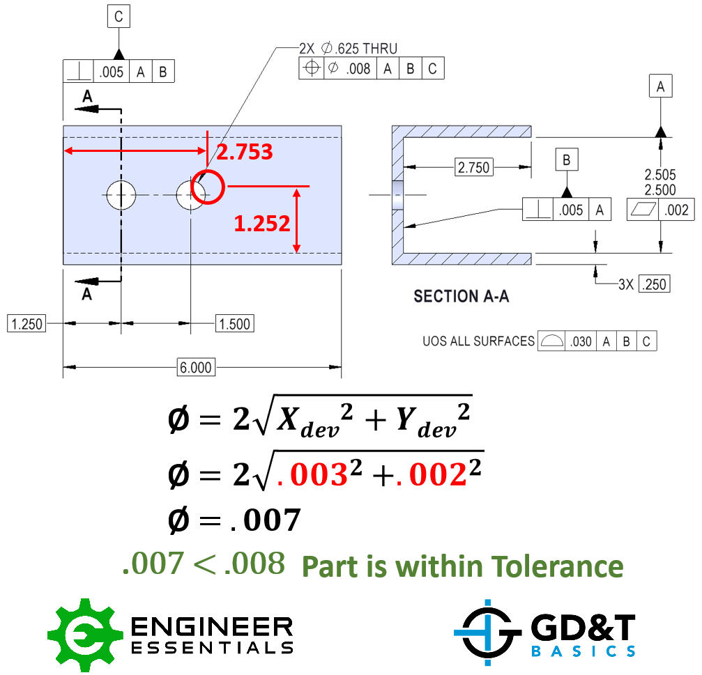
To measure or inspect the feature regarding the position control, X and Y measurements can be taken of the feature with respect to the datum features called out in the feature control frame. These measurements can quickly be converted to a total diametric deviation. If your diametric deviation is less than the specified tolerance, the feature passes. Remember, in order to capture orientation deviations, multiple measurements will need to be taken along the “depth” of the hole or feature.

For the example above, the hole is measured to be off by .003” in X and .002” in Y. Using the shown formula, the diametric deviation is calculated to be .007”. The stated positional tolerance is .008” so the part is with in spec and can be passed.
Position using material condition modifier (MMC/LMC)
The position of a feature of size with MMC is used when a functional gage is ideal for checking the part, typically this is used when a clearance fit is utilized with some sort of fastener.

If you specify the control using MMC, it allows the locational tolerance to be dependent on the size of the feature. You will see position called with MMC very commonly in clearance bolt patterns where location of all the bolts is dependent on the size of the clearance hole. LMC with position is a little less common but often used when controlling a minimum wall thickness is desired.
Position used with Maximum Material Condition becomes a very useful control. Position when paired with the size tolerance of that feature can control the location, orientation, form, and the size of the feature all at once. MMC position is helpful for creating functional gages that can be used to quickly insert into the part see if everything is within spec. While the position tolerance on its own controls how far from true position the feature can be regardless of the size of the feature, position in conjunction with MMC sets a minimum size and positional location of the hole to maintain functional control. It allows the position of the part to be dependent on the feature’s actual size. It does this by allowing a bonus tolerance to be added to the part. As a part gets closer to the MMC, the constraints become tighter, and the hole must be closer to its position. But, if the hole is a bit larger (but still in spec), it can stray from its true position further and still allow proper function (like a bolt passing through).
The tolerance zone is the same as above, a 3-Dimensional cylinder, centered at the true position location referenced by the datum surfaces. The cylindrical tolerance zone would extend through the thickness of the part and would vary in diameter depending on how much bonus tolerance is allowed with respect to the features actual size.
Bonus Round
When a functional gage is used for Position, any difference the actual feature size is from the maximum material condition would be a bonus tolerance. The bonus tolerance for position then increases as the part gets closer to LMC. The goal of a maximum material condition callout is to ensure that when the part is in its worst tolerances, the Position and Size of the hole/pin will always assemble. For instance, if you had a large hole size but were still in tolerance (closer to LMC), you make more bonus tolerance for yourself making the position tolerance larger. You can now have the hole center more out of position due to the bonus tolerance.
Bonus tolerance = (measured hole size – MMC hole size)
Note: Keep in mind the opposite is true for a positive feature like a pin, where the smaller the pin means you have more bonus tolerance.

When a part is checked for position under a feature of size specification, usually a functional gage is used to ensure that the entire feature envelope is within specification. Essentially it is simulating the worst-case scenario boundary of mating parts. If you have a specification for Maximum Material Condition, the desired state is that the surface of the feature will not cross a functional envelope known as the virtual condition. For MMC on a hole this usually means a boundary of the “worst case scenario” that still allows assembly. The following formulas are used to create a gage for position under MMC.
Fixed Gaging of an Internal Feature
For the true position under MMC of a hole:
Gage Ø (pin gage) =Min Ø of hole (MMC)-True Position Tolerance
Fixed Gaging of an External Feature
For position under MMC of a pin:
Gage Ø (hole gage) = Max Ø of pin (MMC) + True Position Tolerance
Locations of the gage pins or holes are given on the drawing as basic dimensions. All gage features should be located at the true positions but sized according to the formulas above.
Remember the further you are from MMC when it is referenced in the feature control frame, the more bonus tolerance you are allowed. For a hole, the larger the diameter, (closer to the LMC) the more bonus tolerance you have for your true position.
Called with or without the Ø symbol
There are two ways position can be called out – either as a distance, in X and Y or most commonly as a diameter. When position is called out as a distance, you are permitted to move from the tolerance in X or Y direction by the allowed tolerance. However, when done this way, the tolerance zone forms a square. This is usually undesirable since in the corners of the square are further from the center than the sides. This also removed over 57% of your tolerance zone! Most commonly, position with reference to location is called with the diameter (Ø) symbol to be called as a cylindrical or circular tolerance zone.
Confused? No worries! For more detail on how bonus tolerances play into these callouts, see our sections on Maximum Material Condition. Or check out our GD&T Course, where we go into deep detail on the position symbol!
Relation to Other GD&T Symbols:
The position symbol is the locating symbol for Geometric Dimensioning and Tolerancing. It locates features of size while also controlling orientation. Paired with the size tolerance of that feature, they control Size, Location, Orientation and Form. It cannot however control the location of surfaces, which is where profile of a surface steps in. It acts much like position does however it can control the Location Orientation and Form of the elements of a surface.
True position controls orientation which means it already controls a feature in the same way as Perpendicularity, Parallelism and Angularity can. The tolerance of both position and these orientation controls refer to a cylindrical envelope of a central axis. However, with true position you can make the tolerance referenced to several datum’s as opposed to just one with axis perpendicularity thus controlling the location as well. When you callout true position using datums on the face, and sides of the part – perpendicularity is controlled as well.
Special Notes:
Here is a sample lesson from our GD&T Basics Fundamentals Course. We explain why it is much better to use a Position tolerance and Basic Dimensions over locating your feature with a coordinate dimension system.
Position is probably the most widely used symbol in GD&T. If you are looking for more information about Position or any of the other symbols, you should check out our GD&T Fundamentals Course. If you like the simplified approach to GD&T on this website and in the video above, be sure to contact us to learn more about the course!

