Total Runout
GD&T Symbol: 
Relative to Datum: Yes
MMC or LMC applicable: No
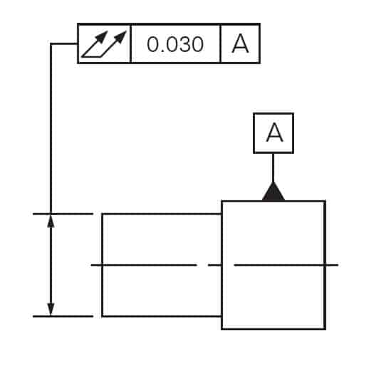
Drawing Callout:

Description:
Total Runout is how much one entire feature or surface varies with respect to a datum when the part is rotated 360° around the datum axis. Total runout controls both the amount of variation in the surface as the part is rotated, but the amount of variation in the axial dimension. Both radial variation and axial variation are measured and held within the tolerance. Total Runout is usually called on a part that is rotated about an axis where the entire surface is critical to be in spec.
GD&T Tolerance Zone:
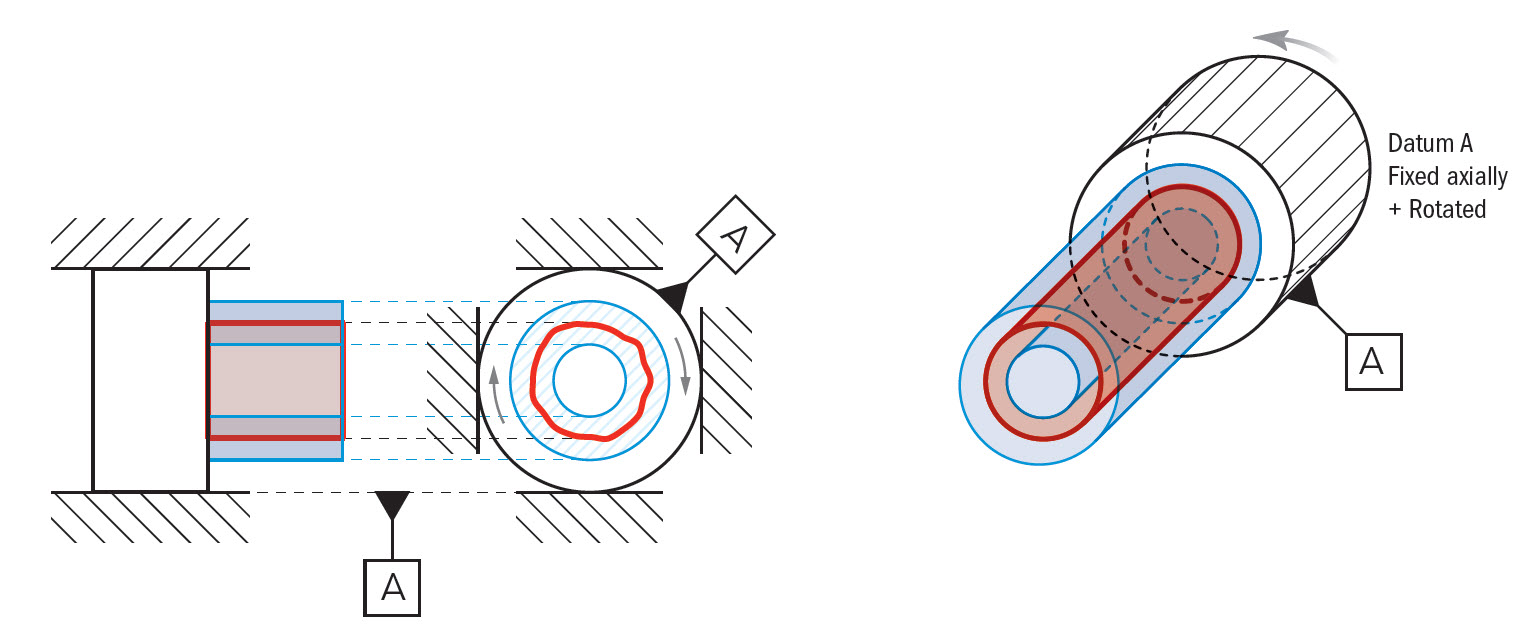
A 3-Dimensional cylindrical tolerance zone that surrounding a referenced surface that is directly derived from either the datum surface or the axis. All points along the surface must fall within this zone when the part is rotated at all times.

Gauging / Measurement:
Total Runout is measured by fixing the datum features (typically an axis) and rotating the part along the rotational axis. The part is usually constrained with a set of V-blocks or a spindle of some sort that will constrain the part while allowing it to rotate. To measure total runout, a series of gauges must be linked to take their measurement in reference to each other – similar to how cylindricity is measured.
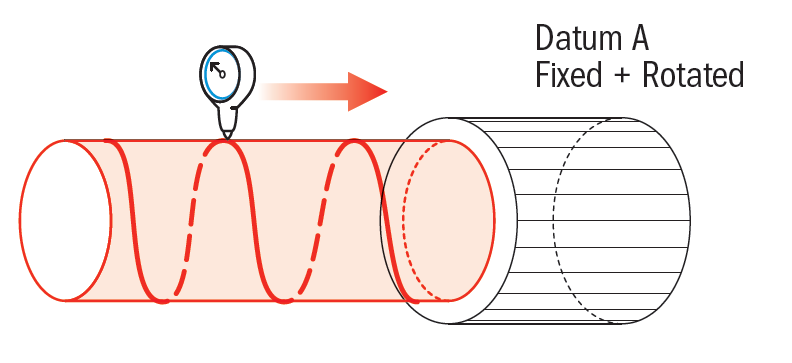
Another method for measuring total runout is to take one gauge held perpendicular to the surface of the part, and slowly move it across the surface of the part axially as the part is rotated. If the gauge varies at any point by more than the total runout tolerance, the part would be out of spec.
Relation to Other GD&T Symbols:
Total Runout Controls: Concentricity, Perpendicularity/Parallelism (feature of size axis), Cylindricity, Circularity, Straightness and of course normal Circular Runout
Total Runout captures Concentricity by controlling the radial alignment of the datum’s axis to the feature’s median points.
Perpendicularity or Parallelism of the two features would be controlled because if the central axis is offset by an angle, the end of the workpiece would runout far more than the side closer to the datum.
Cylindricity would also be controlled because any form variation along a cylindrical surface would show up in the total runout. If the feature is a cylinder, any circularity or straightness would cause the height gauge to fluctuate, even if the part is perfectly coaxial.
Axis Straightness is controlled because any bow in the feature would cause the end of the piece to have a larger runout at the end of the work piece. Surface Straightness would also be controlled because you are now controlling any form variation across the entire surface. (this would control whether the part is a cylinder or a tapered feature)
Circularity is controlled because any form variation along surface, would be picked up by the total runout measurement.
Total Runout is, of course, the 3D version of Runout or circular runout (the term runout on its own, always implies circular runout). While total runout takes the surface of the entire part in a 3D tolerance zone, runout or circular runout only captures the cross-section of the part.
When Used:
Total runout is much less common than circular runout due to the tight constraint it puts on an entire part surface. However it is still a fairly common symbol in Geometric Dimensioning and Tolerancing due to its functional effect of preventing vibration and oscillation. It is very effective at preventing surface taper of a cylinder. Any time a part rotates and has a large amount of surface contact, total runout may be required. Things like large pump shafts, transmission shafts, and complex gears all are cases where total runout is used.
Example:
An axle is normally under high stress and needs to fit evenly in a bushing (not shown). If the referenced surface does not make even, stable contact with the housing bushings the axle will wear unevenly leading to eventual failure. Surface ‘A’(datum) is controlled with a roller bearing and should be axially aligned with the reference surface. Total Runout is called in the same way as Runout.
Referenced Feature is the entire surface for Total Runout.
Similar to Runout total Runout allows the final specification or condition of the part to be called out, thus controlling how the part reacts when it is rotated. The gauge to check this part for total runout would also be nearly identical as the normal runout gauge. The only difference would be that if you moved the gauge up and down the part, or had multiple gauges all fixed to each other, the total gauge indication along the entire surface could not be out.
Gauging the entire surface
Note: Circular and Total Runout can sometimes be used interchangeably to accomplish the same functional goal – Check out our section on Runout for information on how a cross-section is checked as opposed to an entire surface.
Final Notes to Remember:
Combination of Tolerances
Total Runout combines concentricity which is axis to axis relation of a part, with cylindricity. Since Cylindricity is actually a combination of Circularity and Straightness, all of these individual geometric symbols are controlled when total runout is used.
Regardless of Feature Size
Total Runout is always RFS (regardless of feature size) meaning that the boundary formed by the dimensions is the entire part envelope that the part can exist regardless of how large the runout tolerance is. It is directly referenced to a datum axis so a functional gauge or MMC cannot be called out.


