Parallelism
Special Note:
Parallelism actually has two different functions in Geometric Dimensioning and Tolerancing depending on which reference feature is called out. The normal form or Surface Parallelism is a tolerance that controls parallelism between two surfaces or features. The surface form is controlled similarly to flatness with two parallel planes acting as its tolerance zone. Axis Parallelism is a tolerance that controls how parallel a specific parts central axis needs to be to a datum plane or axis. The axis form is controlled by a cylinder around a theoretical perfectly parallel axis. Parallelism is most commonly called out as surface parallelism. However, be sure to pay attention if it is referencing a central axis because it is different! We will only discuss surface parallelism on this page but be sure to check out our page on Perpendicularity to see how an axis is controlled with GD&T.
GD&T Symbol: 
Relative to Datum: Yes
MMC or LMC applicable: Yes
GD&T Drawing Callout:
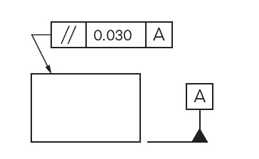
Description:
Parallelism is a fairly common symbol that describes a parallel orientation of one referenced feature to a datum surface or line. It can reference a 2D line referenced to another element, but more commonly it relates the orientation of one surface plane parallel to another datum plane in a 3-Dimensional tolerance zone. The tolerance indirectly controls the 0° angle between the parts by controlling where the surface can lie based on the datum. See the tolerance zone below for more details.
Note: Parallelism does not control the angle of the referenced feature, but only creates an envelope in which the feature must lie.
It is important to determine what the reference feature is (surface or axis) and then what is acting as the datum (surface or axis) to determine how the parallelism is to be controlled.
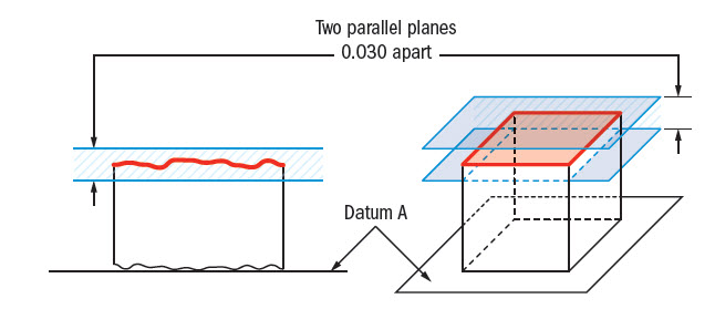
GD&T Tolerance Zone:
Two parallel planes or lines which are oriented parallel to the datum feature or surface. All points that are on the referenced feature must in the tolerance zone.
Remember: Parallelism does not directly control the angle of the referenced surface; it controls the envelope (like flatness) where the surface needs to be. The goal is to ensure all points are within a specified tolerance distance away from their corresponding datum points.
Gauging / Measurement:
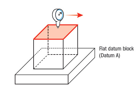
Parallelism is quite simple to measure. Like flatness, a gauge is run across the reference surface or feature. However, unlike flatness, the part is constrained against a granite block or flat plane that acts as the datum surface where it is measured.
Relation to Other GD&T Symbols:
Surface Parallelism
Parallelism is a specific form of angularity only at 0°/180° instead of a called out angle. All the profiles of orientation and are used in the exact same way. All of the orientation symbols (angularity, perpendicularity, and parallelism) all call out the particular feature envelope referenced to a datum.
The Parallel Symbol is also closely related to flatness when referenced/measured surface is flat. When you call out parallelism, flatness is implied (you are measuring a surface variation between two parallel planes = flatness) However the biggest difference is parallelism is measured with respect to a datum, ensuring both the datum and reference feature are always parallel.
When Used:
Whenever two surfaces or features need to work in sync with each other and constant distance must be maintained, parallelism is effective. Whenever you have a part that must always fit nicely between two planes that need to reference each other, it comes in handy. Even though surface parallelism seems to ensure that a flat surface is mating with another flat surface, it can also be applied to two sides of a hole or cylinder to avoid a taper. Any part with two critical flat surfaces such as gears would call out parallelism.
Parallelism Example:
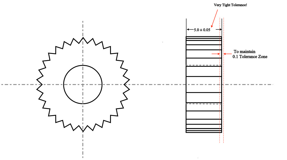
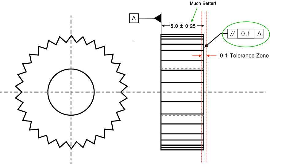
A gear has to maintain constant axial load on both faces. To ensure even contact one side of the gear is held parallel to the other side. To do this without parallelism, the gear width would have to be tightly controlled, which could be very difficult to do.
Ensuring even surfaces without GD&T
With parallelism, you can open up the dimension of the gear and control the faces without rejecting good gears.
Controlling two faces with GD&T parallelism callout.
Final Notes:
Combination of Orientation and Form:
Parallelism is very common in its surface form. When dealing with any flat surfaces, flatness may be called out, but parallelism is usually more critical since the relation of surfaces in an assembly is more important.
Max Material Condition with Axis:
Straightness, Axis Angularity, Axis Parallelism, and Axis Perpendicularity can all be called out and controlled with a gauge in maximum material condition. However only perpendicularity and straightness are used commonly. Please see our page on Maximum Material Condition for more information.
