Least Material Condition (LMC)
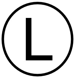
Symbol:
Category: Feature of Size
Definition:
Least material condition is a feature of size symbol that describes a dimensional or size condition where the least amount of material (volume/size) exists within its dimensional tolerance. The callout also overrides GD&T Rule#2 or the Regardless of Feature Size rule.
For simplicity:
If it is a hole or internal feature: LMC =Largest hole size (least material in part)
If it is a pin or external feature: LMC = Smallest size of the pin
Least Material Condition is one side of the dimensional limits on a part. The other side of the tolerance range would be the Maximum Material Condition.
If you want to ensure that two always have contact or a press fit Least Material condition can be called out. It is most often the control of parts that are pressed together to ensure that they always have a snug fit and no clearance.
If you made sure that the LMC of the shaft was always larger than the LMC of the hole, you ensure that there will always be a tight fit between the parts. This creates a condition where you can use a functional gauge to ensure that the external feature is not too small or that the internal feature is too loose.
Use in Geometric Dimensioning and Tolerancing:
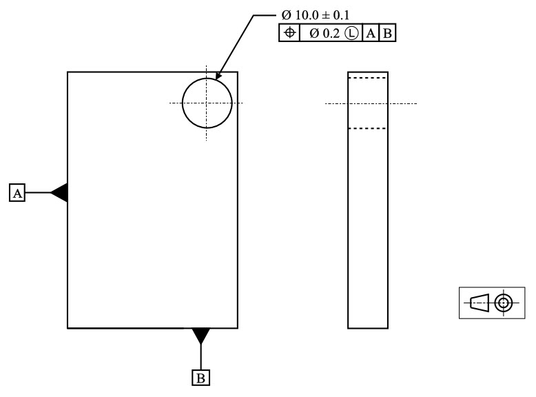
Least Material Condition is fairly rare in geometric dimensioning and tolerancing. There are only a few reasons why a LMC should be called. The most common reason for calling it would be that you have a hole or other internal feature that is very close to the edge of a part. If you call LMC with true position in figure 2 below – you would be specifying that if the hole is at its largest size, it can only vary by as much as the true position tolerance.
Thin Wall Hole Example
However if the hole is smaller than its Least Material Condition, you can apply a bonus tolerance to the part, because now the true center of the hole can be closer to the edge, without minimizing the thickness of the material.
Concept of LMC with No-Go Gauges
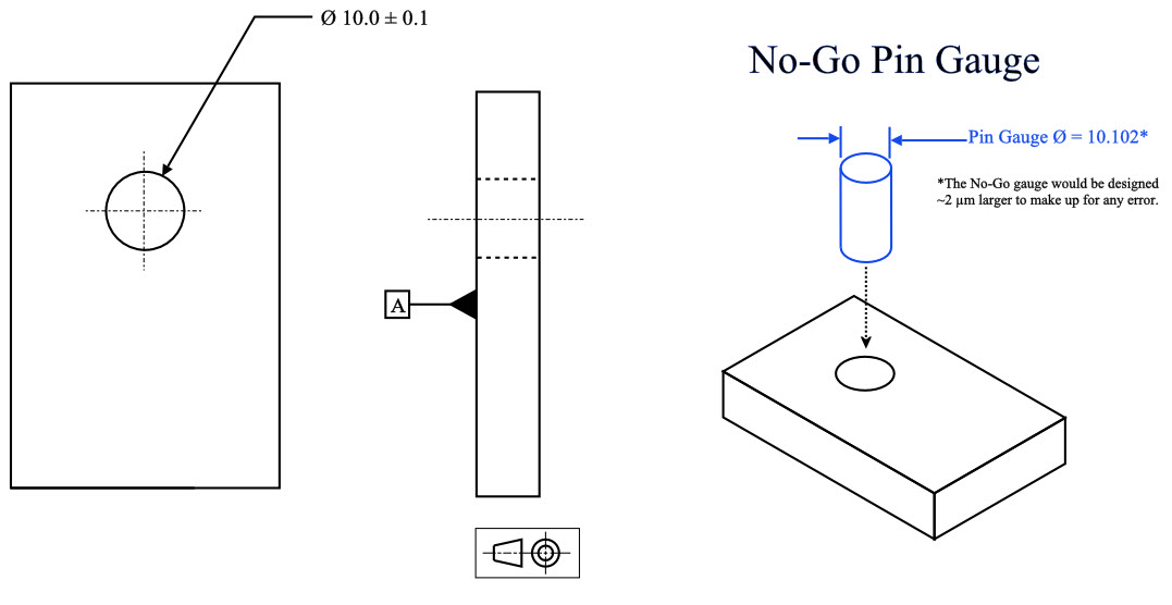
The concept of the least material condition (not the GD&T symbol)comes in handy when a functional gauge is needed to control a part. If you want to limit the size of your feature to insure a proper fit, you can specify the least material condition callout and control it with a specific type of gauge called a No-Go Gauge.
For example if you wanted to ensure that a pin always has a tight fit into a hole, you could design the No-Go hole gauge to mimic the least material condition of the part. This would be a block with a hole of a diameter equal to the pin’s LMC (min Ø). To check the part you would try to insert the pin into the hole. If it doesn’t fit (No-Go) then you know that the pin is large enough to be a tight press fit into the feature.
A No-Go gauge for a hole would use a pin gauge = Hole’s Max Ø
A No-Go gauge for a pin would use a ring gauge = Pins Min Ø
Cannot Combine Gauging with GD&T Symbols
Here is where the weakness of LMC comes out. In maximum material condition you are defining that the size cannot go past the max material size + the geometric callout. This works fine because you are using two tolerances that are positive. However with least material condition this you cannot create a functional gauge that controls both.
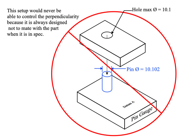
For example if you have a perpendicularity callout and want to also control LMC on a hole, you can check the hole for size with a no-go gauge to ensure it is small enough for a press fit. However if you specify a gauge that allows for a bonus tolerance on the least material condition, you cannot make a no-go gauge also check the perpendicularity, because a No-Go gauge is designed not to fit!

The problem is that GD&T symbols always specify the maximum amount that a part can vary and cannot be combined when you are controlling the a least material control of size. The only way LMC can be called on a feature would be if the least material condition and the perpendicularity were measured and calculated separately. This, however, eliminates the benefit and speed of a gauge.
For these reasons least material condition is seldom used as a control for geometry and size. While gauging is always possible for least material condition size in a production environment, you cannot gauge for both GD&T and dimension at once.
The takeaway should be that in GD&T understanding least material condition as a concept of size is important. The only time you will truly see it is combined with true position on thin walled parts like in the Thin Wall Hole Example above.
Final Notes:
Rare Usage:
Least material condition should only be used when absolutely needed, due to not being able to accurately gauge for size and geometry at once. Least Material Condition is really only used to ensure there is enough thickness between the edge and the inside of the hole.
Features of Size
Least Material Condition is one of three features of size callouts in Geometric Dimensioning and Tolerancing. The other two are Maximum Material Condition and Regardless of Feature Size. All of these specify the condition that the part or feature must be in to apply the specified tolerance.
Regardless of feature size as default
When there is no callout to Maximum Material Condition or Least Material Condition, all parts default to regardless of feature size, meaning the geometric controls exist regardless of how large or small the part dimensions are.


