Feature Control Frame
Definition:
A feature control frame is used in Geometric Dimensioning and Tolerancing to describe the conditions and tolerances of a geometric control on a part’s feature. The feature control frame consists of four main pieces of information:
- GD&T symbol or control symbol
- Tolerance zone shape and dimensions
- Tolerance zone modifiers: material condition modifiers, projections…
- Datum references (if required by the GD&T symbol)
This information provides everything you need to determine how the geometrical tolerance needs to be interpreted and how to measure or determine if the part is in specification.
Example Frames:
Parts of the Feature Control Frame
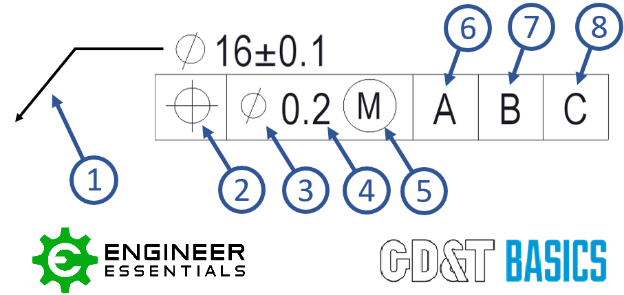
- Leader Arrow – This arrow points to the feature that the geometric control is placed on. (Extension Line or no line as shown)
- Geometric Symbol – This is where your geometric control is specified. See our page on GD&T symbols for a description of each symbol.
- Diameter Symbol (if required) – If the geometric control is a diametrical tolerance, then the diameter symbol (Ø) will be in front of the tolerance value.
- Tolerance Value – The TOTAL tolerance of the geometric control. The unit of measure is based on the drawing standard.
- Feature of Size or Tolerance Modifiers (if required) – This is where you call out any tolerance modifiers in the feature control frame. See the Modifiers section of the GD&T Symbols page for further clarification on these features.
- Primary Datum Feature Reference (if required) – If a datum is required, this is the main datum feature used for the GD&T control. The letter corresponds to a feature somewhere on the part which will be marked with the same letter. This is the datum that must be constrained first when measuring the part. Note: The order of the datum is important for measurement of the part.
- Secondary Datum Feature Reference (if required) – If a secondary datum is required, it will be referenced to the right of the primary datum feature reference. This letter corresponds to a feature somewhere on the part which will be marked with the same letter. During measurement, this is the datum fixated after the primary datum.
- Tertiary Datum Feature Reference (if required) – If a third datum is required, it will be referenced to the right of the secondary datum feature reference. This letter corresponds to a feature somewhere on the part which will be marked with the same letter. During measurement, this is the datum fixated last.
Reading the Feature Control Frame
The feature control frame forms a kind of sentence when you read it. Below is how you would read the frame in order to describe the feature.
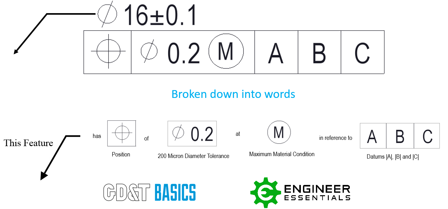
Be sure to check out our individual pages for each GD&T symbol for examples and specific uses of the feature control frame.
Placement of Feature Control Frame
The feature control frame can be placed on feature of size and surfaces. How the feature control frame is placed on the drawing will determine if the geometric control is on a feature of size (FOS) or a surface.
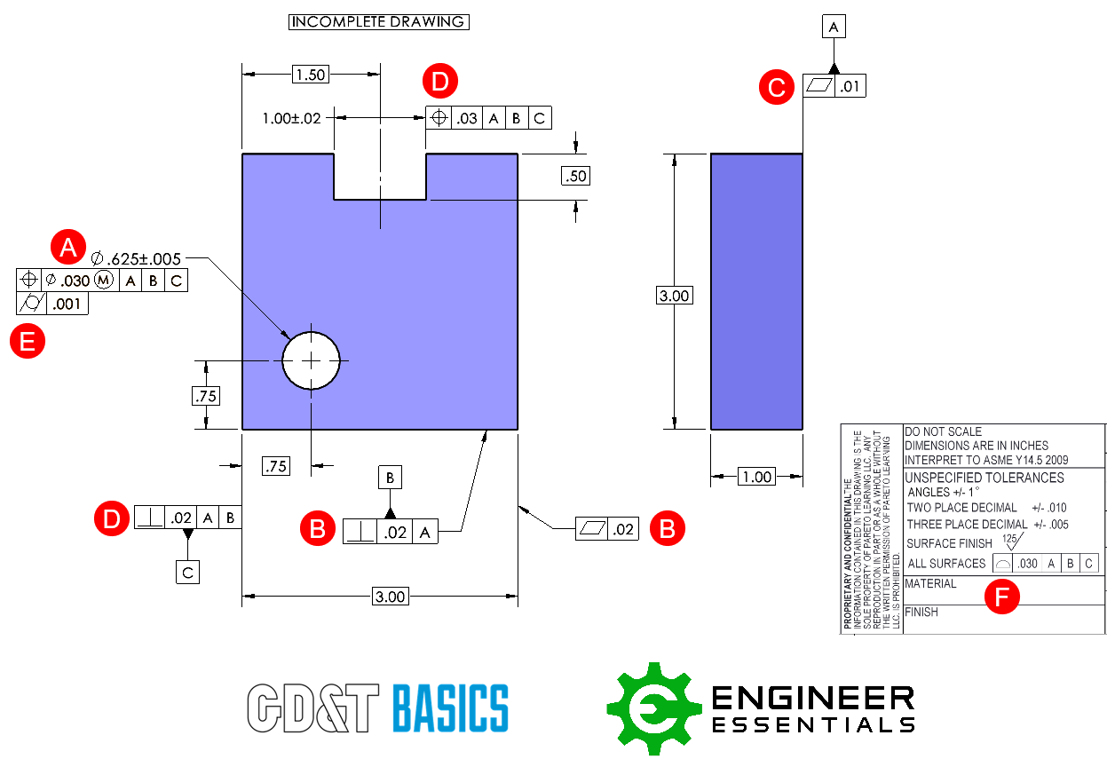
A. Feature Control Frame is located directly underneath or next to note/dimension of a feature. This is controlling a feature of size.
B. Feature Control Frame is attached to feature (or extension line relating to the feature) using leader arrow. Both instances shown here are controlling just the surface.
C. Feature Control Frame is attached directly to extension line of feature. This is controlling the surface associated with the leader line.
D. Feature Control Frame is attached directly to dimension extension line of feature. Take extra care to note that if the feature control frame is directly in line with the dimension, it is controlling that feature of size. However, if it is NOT directly in line with the dimension then it is controlling just the surface associated with that extension line.
E. Feature Control Frame is attached to an existing frame; this is generally used for refinement.
F. Feature Control Frame is placed in a note, chart, or tolerance block
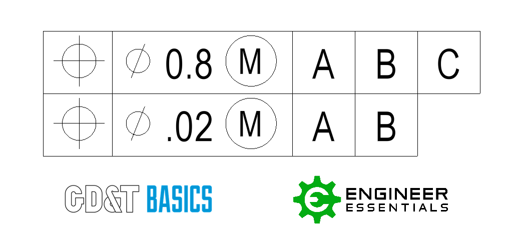
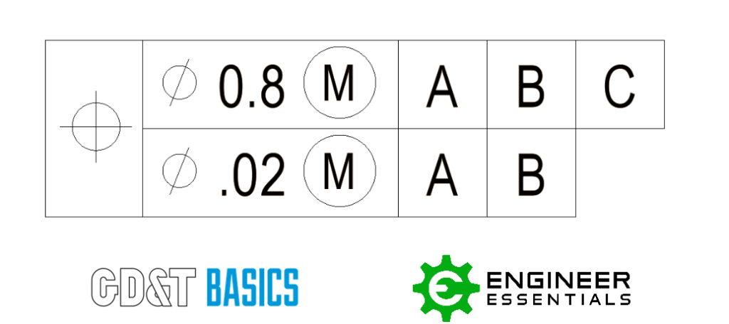
Composite Feature Control Frame
A Composite Feature Control Frame (FCF) contains two tolerance zone frameworks. It is shown to be a composite tolerance because there is one geometric symbol that spans across the two frameworks. Unlike MSS, for the Composite Feature Control Frame the top and bottom operate together. The bottom frame is considered a refinement of the top frame. For more explanation on how a Composite Feature Control Frame is interpreted please refer to our article “Composite Position vs Multiple Single Segment Tolerances”
Multiple Single Segment Feature Control Frame
Multiple Single Segment (MSS) Feature Control Frames (FCF) contain two tolerance zone frameworks. However, the two frames are completely independent of each other. Multiple Single Segment Feature Control Frames will only utilize the position symbol or the profile symbol. For more explanation on how a Multiple Single Segment Feature Control Frame is interpreted please refer to our article “Composite Position vs Multiple Single Segment Tolerances”
