Datum Feature
Symbol: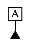
Definition:
Datums are theoretically exact points, axes, lines, and planes or a combination thereof that are derived from datum features. A datum feature is the tangible surface or feature of size (comprised of multiple surfaces or revolved surfaces) that is indicated by the datum feature symbol. You can think of them as anchors for the entire part. They are the surface or feature where the other features are referenced from. It is usually an important functional feature that needs to be controlled during measurement as well.
All GD&T symbols except for the form tolerances (straightness, flatness, circularity and cylindricity ) can use datums to help specify what geometrical control is needed on the part.
Datum Features vs Datums:
Its important to know the difference between Datum Features and Datums. While they are related to one another they are indeed different entities. It is especially important to know this when studying the theories of Geometric Dimensioning and Tolerancing and while setting up a Datum Reference Frame.
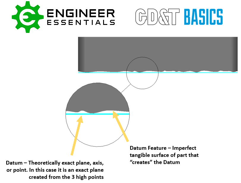
Datums are theoretical and only simulated by Measurement Equipment (Gauge pins, Granite slabs, angle plates, computer-generated planes, etc)
Datum Features are real, tangible features on a part where the measurement equipment would physically touch or measure. They are usually important functional surfaces.
How Datum Features are Shown on a Drawing
The datum features on a drawing are denoted with a series of capital letters. These letters are in boxes and tied to the datum features with a black triangle. This letter will also show up in any feature control frame that uses this datum feature as a reference. A feature control frame will reference as many datums features as necessary to lock in all the necessary degrees of freedom, this creates what is known as a Datum Reference Frame.
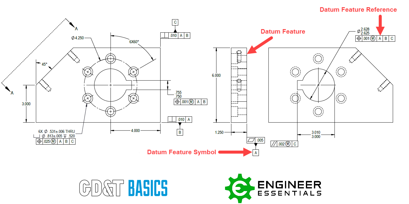
Notation is Important on Drawings
As stated before, datums can be points, axes, lines, and planes or a combination thereof. It is important though that datum features are indicated correctly on the drawing to ensure that the right type of feature is being controlled. Datum features can be either a surface or a feature of size, depending on how the symbol is applied.
Datum Feature Symbol on a Surface
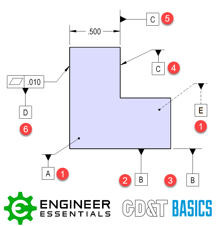
- Point with a solid or dashed leader line with the datum feature symbol placed on it. A dashed leader line indicates the far side surface.
- Datum feature symbol placed directly on a planar surface.
- Symbol placed on an extension line off the datum feature surface.
- Leader arrow with the datum feature symbol pointing to a planar surface.
- Symbol placed on a size dimension but placed offset of the dimension arrows.
- Placed off a feature control frame that is applied to a surface. (Datum feature is geometrically controlled.)
When the symbol is indicated in the methods stated above this means that the datum feature is the surface of the associated with that symbol.
Datum Feature Symbol on a Feature of Size
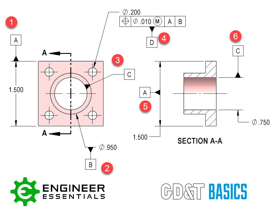
- Symbol is placed on a dimension line directly in line with the dimension arrows.
- Symbol placed on the leader arrow of a size dimension.
- Symbol placed on a non-planar feature of size.
- Placed off a feature control frame that is applied to a feature of size.
- Symbol placed on the arrows of a size dimension.
- Placed as one half in an open-ended size dimension (in line with the arrow).
A few common Feature of Size Datum Features are bores, cylinders, slots, or tabs. These features will generally result in a datum that is an axis or plane (midplane). For example, the datum of the bore labeled as Datum Feature C above is going to be the axis of that bore, NOT the surface of the bore itself. In this example note the tangible Datum Feature is the surface of the bore itself while the Datum is the theoretically exact axis of that cylindrical surface.
