Cylindricity
GD&T Symbol:
Relative to Datum: No
MMC or LMC applicable: No
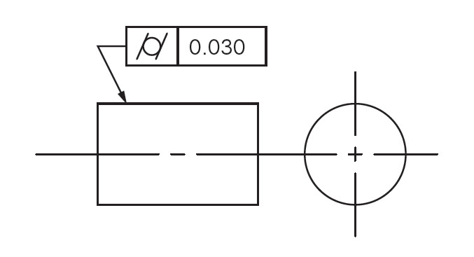
Drawing Callout:

Description:
The Cylindricity symbol is used to describe how close an object conforms to a true cylinder. Cylindricity is a 3-Dimensional tolerance that controls the overall form of a cylindrical feature to ensure that it is round enough and straight enough along its axis. Cylindricity is independent of any datum feature the tolerance needs to be less than the diameter dimensional tolerance of the part. Cylindricity essentially forms a perfect cylindrical boundary around the object that the entire 3-Dimensional part must lie in.
GD&T Tolerance Zone:
Two concentric cylinders that run the entire length of the feature – one inner and one outer, in which all the points on the entire surface of the cylindrical feature must fall into. The entire length of the called out feature would be controlled.

Gauging / Measurement:
Cylindricity is measured by constraining a part on its axis, and rotating it around while a height gauge records the variation of the surface in several locations along the length. The height gauge must have total variation less than the tolerance amount.
Relation to Other GD&T Symbols:
Cylindricity is a merger of circularity and surface straightness. It is the 3-Dimensional version of circularity along an entire cylinder length. While circularity only is concerned with individual measurements around the surface in one circle, cylindricity takes into account how straight the axial portion of the cylinder is. Thinking of stack of coins, cylindricity would measure to make sure that the entire stack is straight up and that every coin is round. Circularity would only be measurements of the roundness of the individual coins.
When Used:
Cylindricity is a fairly common callout for shafts, pins and any critical cylindrical element. When a part needs to be both round and straight along its axis, such as a sliding shaft, or a dynamic locating pin, cylindricity is usually called out. You will see this GD&T symbol very often in automotive drawings and mechanical systems.
Example:
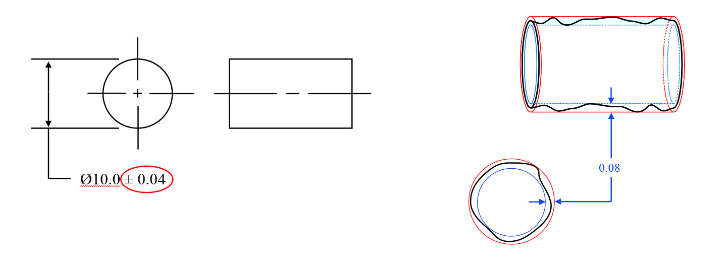
If you had a bushing that was to be pressed into a housing, the bushing would take the form of the housing bore when inserted. To ensure that the bushing maintains its round shape, and wears evenly along its surface, the housing bore needs to be very cylindrical. To do this without Geometric Dimensioning and Tolerancing you would need very tight dimensions on the diameter of the bore, which may be very hard to control when being machined (and expensive)
 Cylindricity example 1: Controlling cylindricity without GD&T Symbol
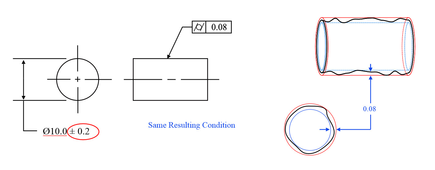
 Controlling the circularity and the straightness of the bore with cylindricity.
This GD&T control allows the diameter tolerances of the part to be opened up much larger, and better controls the entire length of the bore. You can now accept a much broader range of hole sizes as long as the cylindricity is met.
Final Notes:
Statistical Tolerances:
Because cylindricity specifies the form of the surface, it must be considered when calculating a statistical tolerance stack. For example, if you have a part with a diameter and cylindricity callout, you must input both into your statistical stack since the cylindricity can contribute to a large part envelope than just the diameter tolerance alone. There are different theories on doing this and how to implement it; however, it can make a slight impact on skewing the results higher. Normal tolerance stacks do not require this since due to the envelope principle; the maximum radial envelop cannot exceed your maximum diameter tolerance due to rule #1 of GD&T.

